Cable Jam Ratio Paper
The Concept of Jamming and How it Impacts a Cable Pull...
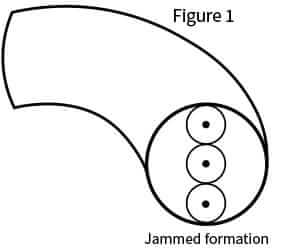
Picture this: three cables scrunched comfortably in a triangular configuration scooting down the conduit until they encounter a bend. The bend forces the three cables to splay out into a side-by-side configuration. If the combined width of the three cables is big enough, the cables can wedge against the conduit walls, stopping the pull…cold.

Jamming is a phenomenon that happens in pulls of three cables into conduit with at least one bend. The forces required to pull through a jam will damage the cables, conduit, or both due to the geometry of the cables in relation to the conduit as shown in Figure 1. So, if you are pulling three cables at one time, you’ll need to plan ahead to avoid this risk.
To figure out your jam ratio, use the following equation: jam ratio equals conduit ID divided by average cable OD. For example: three 1-inch (2.54 cm) cables in a 3-inch (7.62 cm) conduit yields a 3.0 jam ratio. Jamming only occurs within a jam ratio range of 2.7 to 3.1. Why? If the three cables are small enough in relation to the conduit, they can’t wedge. If they’re big enough, they can’t be forced out of their triad.
The Pull-Planner™ software averages cable OD and notifies the user with a conclusion that jamming is either “not possible,” “not probable,” or “is likely.” You can reduce the possibility of jamming by changing the conduit size or by triplexing the cable.