Model and Analysis of Duct Displacement Factor in Fiber Optic Cable Pulling—Part 1
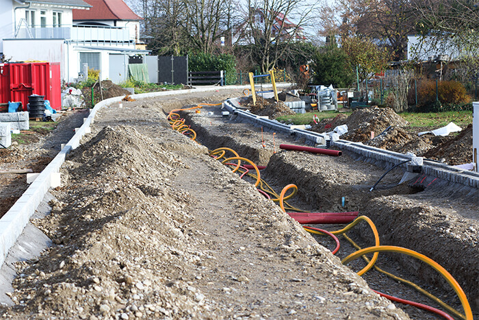
Because conduit is pulled from a reel when being installed underground, it’s important to recognize that there may be undulations that create low-angle bends.
Why is duct displacement significant to underground installation of fiber?
Because conduit is pulled from a reel when being buried underground, it’s important to recognize that there may be undulations that create low-angle bends. During installation, the conduit can appear like it’s running straight, but when pulling cable long distances, slight bends in the conduit can add up and produce higher pull tensions.
| Related Content: Model and Analysis of Duct Displacement Factor in Fiber Optic Cable Pulling—Part 2 |
What is different about fiber optic cable pulling?
When pulling underground fiber optic cable, we often want as long an uninterrupted span of the cable as we can get. So, if the cable comes on a 10 km (32,800 ft) reel, we want a full, unbroken 10 km span to eliminate any splice-induced attenuation.
To determine the pulling lengths that are possible, we can use the “cable pulling equations” to estimate cable pulling tension based on friction, cable weight, and conduit run details. Such estimates have shown good correlation with field-measured tension when heavy cable is pulled into hard-sided conduit, but the length of the runs is much shorter than we want for fiber. Plus, fiber optic cable is much lighter weight than twisted pair copper cable.
The equations predict that fiber can be pulled much longer distances than is possible today. Assuming a typical 600 lb. (2.7 kN) maximum tension, theory says it should be possible to pull fiber cable (with a typical weight of 100 lbs/1,000 feet (150 kg/km)) some 30,000 feet (9+ km). This estimate uses a friction coefficient of 0.2, and that is not unreasonable as much lower friction coefficients have been measured using Polywater’s high-performance, fiber optic pulling lubricants.
Real field experience shows more typical pulling distances of 1,500 to 2,000 feet (0.46 to 0.61 Km) to keep tensions under 600 lbs. (2.7 kN), even into a new, well-placed duct system. Why do pulls of fiber optic cable show such poor correlation with calculations based on the theory?
| Related Content: Measuring Cable Pulling Friction with a Reel Test |
The duct factor
Fiber optic cable is generally pulled into continuous, reeled, PE or flexible PVC duct. When this duct is pulled from the reel and trenched, plowed, pulled, or bored, it retains some reel memory that produces slight, but regular, displacements or undulations. While a run appears “straight”, the duct reel memory displacements behave like low-angle bends. With the long pulls typical of fiber optic, these bends add up, and produce higher tension than expected.
To better understand this, let us look at the simplified form of a cable pulling bend equation.
Conduit Bend Tout = Tin eμϴ
Where:
Tout = Tension Out
Tin = Tension in
μ = Coefficient of Friction
ϴ = Angle of Bend (radians)
e = Naperian Log Base
We see that if we double the bend angle, the multiplier squares, and 10 times the angle increases the multiplier to the tenth power. The angle is in an exponent.
| Related Content: Planning Cabling Projects Improves Success and Safety |
Modeling duct factor.
To quantify this in fiber optic pulling, we need to model the duct displacement, as shown in Figure 1.
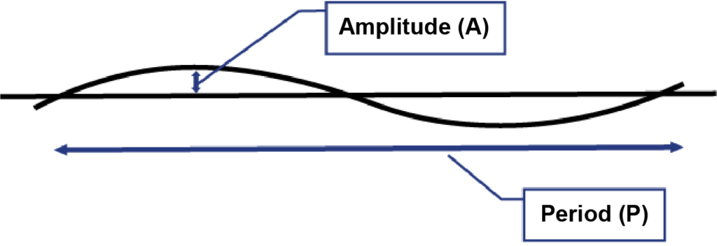
Figure 1 – Model of Regular Duct Displacement
This model treats the displacement as a “repeating wave” running the length of the conduit. This wave is described by its “amplitude (A)”, the maximum displacement from a straight line, and its “period (P)”, the repeating distance from peak to peak. We might guess that P is related to the duct reel diameter and A to the method of duct installation.
Field placements have shown several variables that affect the amplitude and period. These include duct type, wall thickness, reel diameter, duct OD, and placement method. For reeled innerduct dropped into an open trench, a wave with an amplitude as high as 12 inches (300 mm) and a repeating period of 20 feet (3 m) has been observed. The same duct pulled into 4″ (100 mm) Schedule 80 PVC might only have an amplitude of 0.75″ (20 mm) every 20 feet (3 m). For the thick-wall ducts used for “plowing” and directional boring, the regular displacements cannot be easily observed but are known to depend on soil type and rockiness, and they can be measured using geolocation robots run through the duct.
| Related Content: Coefficient of Friction in Cable Pulling Tension from Conduit Bends |
This model allows us to quantify the “bend” in a “straight” run based on the displacement amplitude and the repeating period, and then to use the pulling equations to determine the effect of that bend. The next issue will work that math and show the analysis.
In part two of this series, we show how total angle of bend per period is related to effective bend per length of duct. This information can lead to improved tension prediction with real-world application.