How Temperature and Water Influence the Aging of Transformers
A variety of factors influence the aging of transformers with oil/celluosic systems and accelerate the aging process.
1. Introduction
A variety of factors influence the aging of transformers with oil/celluosic systems and accelerate the aging process. In this article we will discuss:
1. Specific influences of temperature and water on transformer aging.
2. Pathways by which moisture and water enter the transformer.
3. How temperature and water accelerate transformer aging.
We will also describe how to:
1. Reduce the influences of these accelerators.
2. Dry waterlogged transformers.
3. Minimize the influences of temperature.
4. Prevent accelerated aging altogether.
In addition, we will outline factors that should be specified early in the transformer design phase to ensure a reliable asset over the long term. We’ll address acid and oxygen and their role as accelerators in a subsequent article.
2. The Influence of Temperature
High temperatures have a significant impact on the transformer aging processes.
2.1 Montsinger’s Rule
In the 1930s, Montsinger helped to quantify the degree of accelerated transformer aging due to temperature. He determined that a temperature increase of 8°C will halve the service life of a transformer.
Montsinger also showed that the aging process is negligible at temperatures below 50°C. These principles continue to hold to this day, even with the development of new materials used in transformers in the intervening 70 years.
Based on these principles, let’s generalize that a 10°C increase will cut the service life in half and that monitoring a transformer’s temperature makes sense only when it is over 50°C. Below this temperature, aging will be so slow as to rule out any failure at any time during the transformer’s estimated service lifetime.
| Related Content: How Oxygen and Acids Influence the Aging of Transformers |
3. The Influence of Design
There is no such thing as a typical or identical trajectory of transformer aging, because there is no such thing as a “standard” transformer. As stated above, temperature is an aging accelerator. More precisely, aging depends on the temperature in the hottest area of the transformer. It makes no sense to consider an average temperature. Aging is not average and will always go together with a specific temperature at a specific location inside the transformer.
To assess transformer one needs to start with the hottest zone. If the cellulose has lost its mechanical strength due to thermal aging at a certain location in the transformer, it will not matter if the degree of polymerization (DP) value is still “good on average.” In such a case, the transformer will not be “on average” broken. It will completely fail unless it has already reached its end of life (EOL will need to be repaired at the very least. Therefore, it is important to determine during the specification stage of the transformer that the design of the internal cooling system be optimized for the conditions in which the transformer will operate.
It will be impossible to correct a faulty internal cooling system, which we will address in detail in Section 5.1.
The Influence of Water and Moisture
4. Water as an Aging Product
Many papers have been published on the subject of “Water as an Aging Product.” Some claim that water content can be used to assess a transformer’s age. The technical basis of such claims seems plausible enough since it is a matter of chemistry. Every time long-chain cellulose molecules are broken up by thermally driven chemical processes, water is released. As a result, it could be said that the aging process is a source of water inside the transformer. What is less clear is the extent to which this phenomenon, called cellulosic pyrolysis, plays a significant role in waterlogging transformers.
From my personal experience, all old transformers show increased water content, but pyrolysis is not a significant source. External sources of water/moisture are more important in accelerated aging of transformers.
4.1 Water and Moisture Gateways
Water content in different transformers of similar age and operating conditions is by no means similar enough to infer a universal aging mechanism. Because of the differences in water content in transformers, we must conclude that external causes generate the differences.
The most heavily waterlogged transformers are those that have undergone frequent load changes and thermal stress in the tank area. Transformers with critical components, such as the L.V. high-current bushings in electrolysis plants, are inherently leaky and show higher water content. The same applies to generator step-up (GSU) transformers.
On the other hand, grid and transmission transformers normally have rather low water content. These transformers are both hermetically sealed and openly breathing transformers with similar water content after many years. This indicates that most of the moisture/water in the transformer comes from external sources.
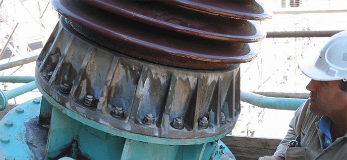
4.2 Cooling Water
Another source of water is from leaking water coolers, especially those that are single walled. It makes no difference that the static pressure needs to be higher on the oil side than on the water side. Pipe elbows are especially prone to micro-cracks and high partial pressure which allow water to penetrate to the inside of the transformer.
| Related Content: Mapping Transformer Populations |
5. Preventing Accelerated Aging
To effectively reduce premature transformer aging, accelerators must be detected and managed. This needs to be addressed early in the design stage. It is critically important to insist on correct sealing system designs on the one hand and low thermal loads on the other. With an adequate cooling system, maximum temperatures can be kept lower, thereby significantly extending the service life of a transformer.
5.1 Ensuring Correct Thermal Design
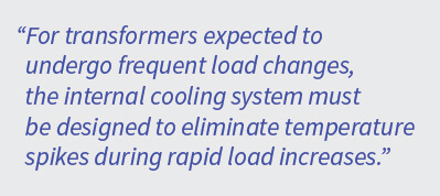
The manufacturer must prove, even during the project design phase, that the temperature profile of its transformer is appropriate. None of the admissible temperatures should ever be exceeded at any point, not even for short time periods. Even at the technical specifications stage, it is imperative to select the cooling system appropriate to the transformer’s function. For example, for transformers expected to undergo frequent load changes, the internal cooling system must be designed to eliminate temperature spikes during rapid load increases, e.g., OD (Oil Directed) cooling. For transformers where the oil needs to be pumped, e.g., OFWF (Oil Forced/Water Forced), or in the case of remotely installed oil-to-air radiators, the cooling in the windings must be based on ON (Oil Natural) design so that the oil is distributed as evenly as possible inside the transformer.
To check a transformer’s thermal design after completion, fiber optics are used to generate an extensive profile of the temperatures inside the transformer. Ideally, there should be at least several sensors in each winding per leg. The optimal sensor distribution is on top, 2/3 of the upper half, 2/3 of the lower half, and on the bottom. Typically, the middle leg in a three-phase transformer should be equipped in every winding (HV, LV, tertiary, fine, and coarse tapping windings).
5.2 Monitoring Gassing Behavior
During operation, a transformer’s gassing behavior will provide conclusive data about the effectiveness of its design. The technical specification of the transformer must stipulate that the presence of thermally induced gases during operation, e.g., C2H4, C2H6, C3H4, C3H6, C3H8, is prohibited. Their presence indicates temperatures above 150°C. The value of these gases in dissolved gas analysis (DGA) must be “0”. If not, the thermal conditions present in the transformer are unacceptable. I don’t advise applying any limits on values.
5.3 Reduction of Water Content
If testing reveals increased water content, e.g., during the oil quality test, the water content must be reduced. This value is by the sampling temperature and must always be checked using the Nielsen diagram.
5.3.1 Measurement of Water Content
Since water is present in the transformer, its value needs to be collected directly or indirectly from the transformer. The water content of an oil sample alone tells us nothing.
A useful method to measure water content is to use an oil moisture assessment in conjunction with a Nielsen diagram. To do this, the temperatures at the top and bottom of the transformer need to be monitored over an extended time period to ensure that the transformer load is balanced. Systems using a capacitive probe are particularly helpful for this purpose. The measurements must be recorded in the ppm range.
A tried and tested direct dielectric measurement system for water content is the fire and gas detection (FDS) system. The data from this measurement can be regarded as accurate and can be supported by the method above.
The following data should be used as reference values for the assessment of water content:
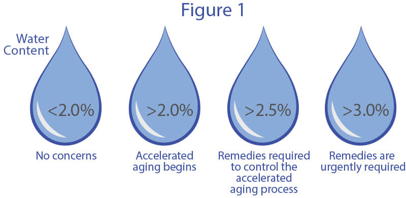
Remedies and Sealants
If the water content exceeds the appropriate level, the cellulose requires drying. There are different drying processes available. The simplest and least problematic method is to use bypass systems. They extract water from the transformer during operation by draining it through the oil path. The use of oil treatment plants is not advisable because they only dry the oil and cannot remove more than 1% of the stored water from the transformer.
Proper sealing of the transformer must be a high priority to prevent the ingress of humidity and water. The use of technologies designed specifically for transformer sealing will ensure the long-term performance of the transformer.
Key factors in choosing transformer sealants include the following:
- High adhesion of the sealant to the various components inside the transformer.
- High breakdown voltage (BDV) to avoid partial discharge.
- Compatibility with both mineral and ester insulation fluids
- Ability to adhere to a variety of materials like copper, brass, steel and rubber
| Related Content: Cost Effective On-Site Leak Repair of Power Transformers |
-
6. Examples
The examples below demonstrate the effect of moisture and temperature and how important it is to monitor them and to put measures in place to lessen their impact.
6.1
A 60 MVA 150/20kV transformer fails after 15 years. There were two reasons:
1. inordinate temperature increase for the climate in which the transformers were located
2. poorly distributed internal cooling
The DP values were taken from the outside windings of a functional phase.
6.2
A 300 MVA 500/150kV ONAN/ONAF/OFAF Interbus coupler bank fails after 15 years.
An inspection showed that the final root cause may have been a very low DP value. The temperature settings and the daily temperature curves, show that the transformer’s design as quite stable and able to withstand daily high temperatures up to nearly 100° at the following settings:
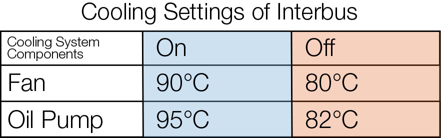
The graph below illustrates the temperature profile and the positive impact of properly designed cooling systems.
![]()
7.0
The DP profile of the regulating transformer 110/20kV 45 MVA ON, cooled in a rectifier transformer of an aluminum plant after 40 years in service, resulted in perfectly distributed internal cooling.
7.1
Improvement of the condition of a 35MVA rectifier transformer under treatment and conservation. The graphs below show that it was possible to keep the breakdown voltage high (between 60 and over 80kV) and the water content low until the present day. The reduction of furan content means that their production was highly limited, keeping the DP value stable. A similar transformer, where paper samples could be analyzed, proved that from the start of the treatment (reducing water and oxygen), the DP value was kept stable, confirming this fact.
On the left side of each of the graphs below is shown the state of the variable (Graph 2: Breakdown Voltage, Graph 3 Furanic Content) using an inefficient oil purification treatment process. The effect on both breakdown voltage and furanic content using this process was only temporary. The right side of each graph shows how using a bypass system with drying, partial degassing, and permanent particle filtering capabilities conserves both breakdown voltage and furan content at acceptable levels over long periods of time.
![]()
![]()
Temperature and water are considered among the most harmful aging accelerators in oil-cellulose systems. To keep their effects in check, you need to implement maintenance measures, especially during the design phase. Sealing a transformer to prevent the entry of water and/or humidity is an important step when servicing transformers.
Additionally, the temperature settings of cooling system controls need to be checked regularly to avoid unnecessarily high thermal loads. Keeping the radiators clean is an important step in efficient functioning and critical to keeping temperatures in the desired ranges. We will continue to guide you through additional accelerators and how they contribute to transformer aging as the series of articles continues.
| Related Content: Transformer Leak Repair Story from Polywater® |
Have any questions?
References
1. Loading Transformers by Temperature, V.M. Montsinger, A.I.E.E Journal, April 1930.
This article was originally published in Transformers Magazine, and is republished here with permission.
©2019 American Polywater Corporation. Daemisch series paper #2.