Submarine Cable Landfall Installation: Testing Cable Lubrication for Challenging Cable Pulls
Explore submarine cable landfall installation, shore pull methods, cable lubrication, and COF testing to improve planning and installation performance.

The demand for submarine power cables is surging, driven largely by the expansion of offshore renewable energy and new cross-border interconnectors designed to diversify regional energy supplies. Offshore wind parks provide a highly consistent, high-capacity source of renewable energy by tapping into faster and more reliable marine winds. As just one example, an interconnection between France and Ireland covers 300 miles (480 km) and helps grid operators balance generation and demand more efficiently. Demand for these resources continues to increase. As more submarine cables (for both power and telecommunication) are installed and connected to the onshore grid, methods continue to be tested and improved. Polywater® plays a part in this effort.
Managing the transition from offshore to onshore during the landfall operation is a critical consideration during installation planning. Methods are evolving. In the past, open trenching was a common and economical method to install the cable during landfall operations. This method requires direct access to the beach. In areas with high tidal range and energetic wave action, trenching can be problematic. Trenching impacts public areas and so that public opinion is not favorable. Permitting has become more difficult. New onshoring techniques are evolving.
Submarine Cable Landfall Installation Methods
In many landfall installations, demanding environmental restrictions drive alternate installation techniques. One increasingly common installation technique is horizontal directional drilling (HDD). This method is complex, but much less disruptive to the beach. HDD is the most common trenchless technique used in submarine cable landings. It is a technical installation method that requires planning and diligence. Drilling mud must be captured. Other important alternative methods are Micro Tunneling and Direct Piping. These methods can be more adaptable to difficult soil conditions. They are also interesting because they allow several cables to be installed in the same tunnel.
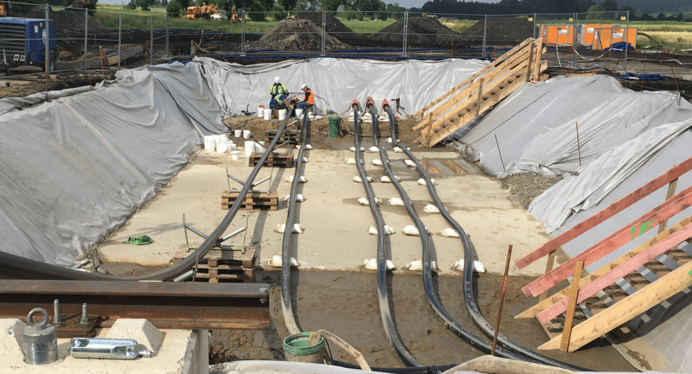
Because the transition joint bay requires a lot of space, it is often located well inland. The landfall design is driven by terrain and other civil considerations. This, in turn, drives the choice of conduit, either polyethylene or steel, and the pull distance. This section of cable pulling is often long and difficult. It requires special planning. As different methods to install landfall cables evolve, techniques to pull submarine cable through duct are also developing.
| Related Content: Underground Cable-in-Duct Installation: 5 Trends to Consider |
Polywater has experienced an increase in these installation projects over the last five years. We have had multiple conversations with designers, engineers and installers as methods continue to improve. These are difficult designs to plan. There are many unknown factors. As we continue to study and test, Polywater hopes to get more answers and learn more about the benefits of lubrication in these installations.
How Submarine Power Cables Differ from Land Cables
Submarine cables are a relatively new fixture in the Polywater lab. Testing has expanded significantly over the past few years. Submarine cables are designed differently than underground land cables. Submarine cables are designed to withstand environmental extremes and external water pressure. These cables are built to address extreme mechanical considerations including the forces from the axial loads as the cable is installed and bending and torsion forces from wave action and undersea currents.
Common design elements of submarine cables include:
• Submarine power cables are heavy and typically weigh 50-160 kg/m (35-105 lbs/ft).
• Cables have a metallic sheath, a polyethylene sheath, and metallic tape reinforcement. These elements protect the cable from water ingress and preserve the electrical properties.
• Submarine power cables are armored with wires designed to improve tensional stability and torsion balance.
• The cable’s outer sheath is typically layers of polypropylene yarn wrapped into an asphaltic coating. This adds further mechanical and corrosion protection.
• Fiber is constructed in the cable to measure thermal effects and detect movements near the cable.
Maximum pulling limits for cables pulled through duct during landfall installation are set by the cable manufacturer. Some cable manufacturers consider the fact that the force is transferred to the armor and allow for higher pulling tensions. In any case, cable tensions are carefully considered during installation planning.
| Related Content: 4 Strategies for a Successful Cable Pull on New Construction Projects |
Shore Pull Operations for Submarine Cable Installation
The cable route from the cable laying vessel to duct entry differs from project to project. How the cable reaches the transition joint bay inland during the “shore pull” highlights the engineering ingenuity in this field. It varies by equipment, shore conditions, and other considerations. Below are two representative installation scenarios.
Vessel Feed
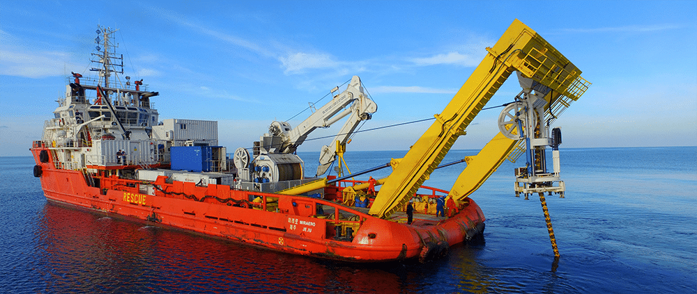
In this shore pull, the cable is paid out from the ship’s carousel through a tensioner device and then through the vessel chute as the cable is pulled through the HDD using a shore-side winch. The cable is lowered underwater and is pulled into the HDD entrance at the shore landing. Lubrication may take place onboard the ship before the cable is fed through the vessel chute.
Cantilever Assist
In this shore pull, a duct overlength is created and hung off an assisting cantilever platform called a jack-up vessel. The cable is paid out from the ship’s carousel through the tensioner and up to the jack-up vessel. In this case, the cable is lubricated as it enters the HDD duct near the cantilever on the assisting jack-up vessel.
Cable Lubrication During Landfall Installation
In either case, the lubricant must persist and continue to function in an aqueous environment. During the planning analysis, there is special attention to the cable configuration and its integrity. Some of the limiting criteria include:
• Maximum allowable cable tension
• Minimum bending radius
• Maximum sidewall pressure (SWP)
Once the cable reaches the duct, it is pulled at a low speed. The water offers buoyancy and there is little drag. Because of the low pulling speed, the process is considered quasi-static. Even with the buoyancy effect, the cable is heavy and is pulled a long distance. It is important to review the pulling tension during the design and planning phase of the operation. It is helpful to have a good estimation of the coefficient of friction (COF) expected between cable and conduit.
| Related Content: Advances in Friction Testing for Ducted Cable Installation |
Laboratory Testing of Submarine Cable Lubrication
Replicating Shore Pull Conditions
At Polywater, we try to understand cable installation conditions and replicate them in our laboratory. This helps us design lubricants targeted for specialty end uses. It supports our work in guiding engineers on COF estimation and supports installers with best cable lubrication techniques. Trying to assign a coefficient of friction value for a shore pull installation is difficult.
Recent COF testing at Polywater represents 3 different cable manufacturers with 3 different projects. In two of these cases, the plan is to pull cables into steel ducts, adding to the difficulty of the installation.

The outer cable surface and the conduit surface are key to testing COF. Submarine cables are wrapped with polypropylene yarn pressed into an asphaltic (bitumen) coating. This layer adds further protection against corrosion and mechanical forces. It adds abrasion and friction resistance. This layer is sometimes called the serving or bedding. It is one of the many unique features of submarine cables which is of particular interest to Polywater as we test for COF and the effectiveness of lubrication.
The polypropylene yarn surface is much different than a typical land cable. The yarn creates a textured surface with more surface area for a lubricant to cover. To replicate the surface conditions, different samples of either submarine cable or polypropylene yarn were obtained from the cable manufacturers. Submarine cables or lab “cable” samples made from layers of wrapped polypropylene yarn were tested. While differences in the yarn were observed, no major differences in performance were noted in the test results.
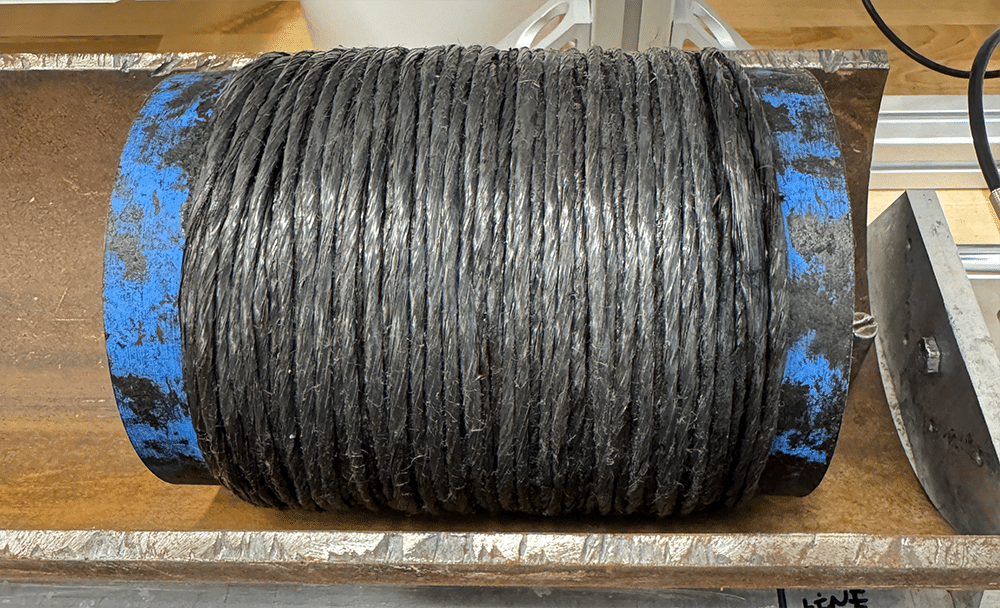
The lubricated polypropylene surface was tested dry and after soaking in salt water for 24 hours or tested while immersed in water. The steel duct evaluated had an oxide layer (rust) as a worst-case scenario. The information shared below is just the beginning part of our research.
Coefficient of Friction (COF) Results
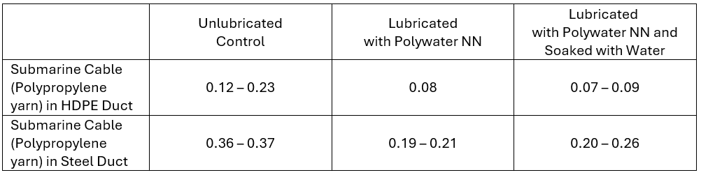
One of the first things to notice in this data set is the use of Polywater NN Lubricant produces consistent results across multiple cables. There is some loss of effectiveness after the water soak, but performance continues to show improvement over the unlubricated control.
Use of Polywater NN shows a COF reduction of 30% to 65% in HDPE duct and 40% to 50% COF reduction in steel duct. After the water soak test, Polywater NN remains effective. The lubricant persists in this laboratory version of an aqueous environment. After the water exposure, Polywater NN COF results are within 25% of the dry, standard lubrication test.
| Related Content: Optimizing Cable Installation: The Importance of COF and Material Testing |
This accounts for some of the field conditions, but not all. Laboratory testing shows what might be possible in a best-case installation scenario. One aspect of this testing is how well the lubricant can coat the polypropylene yarn without being washed away since submarine cable installation is in such an extreme environment. Another question we continue to pursue is whether the lubricant can add yet more protection to keep the yarn from wearing and fraying.
Future Research on Submarine Cable Installation at Polywater
Our work is just beginning. Next, we will gather field tension data from submarine shore pull installations and compare them to laboratory results. Building this knowledge base will assist engineers in future designs. Ultimately, a deeper understanding of the installation process drives product development, allowing us to engineer superior lubricants for submarine cables. What is your experience? We would like to hear about it.