3 Cable Installation Methods That Impact Tension Calculation
Discover how modern cable installation methods—HDD, pushing, and floating—impact tension calculations and influence safe, efficient cable design.
The use of cable tension equations is a key part in the planning phase of cable installation. It analyzes and predicts cable behavior to determine installation feasibility. Accurate cable tension prediction is essential to protect cable integrity, improve worker safety, reduce project costs, and ensure the optimal performance of the cable over its lifetime. Additionally, accurate calculations can facilitate longer installation distances that result in labor efficiency and fewer joints. Traditional equations remain the industry standard for calculations, but newer installation methods introduce variables that require adjustments to these models. Understanding how each method impacts tension ensures reliable performance and reduces installation risks.
“The knowledge of the pulling tension is not only essential to plan the actual lay, but also to assess the suitability of cable design/ route design/ laying methodologies.” (CIGRE TB 889)
Proven Cable Tension Equations Used in Modeling Installation
Most cable installation guides and software planning tools utilize equations developed in the mid 20th century. These equations calculate the force of gravity and physics as cable is pulled around a bend. This calculation approach is rooted in history, is well established, and has been an integral part of cable-in-conduit design for over 75 years. The equations first developed by F.H. Buller (1949) and then expanded on by R.C. Rifenburg (1953) describe cables pulled through sloped duct, horizontal bends, as well as vertical concave and convex bends. These “Rifenburg” equations measure the force based on the cable’s angle of entry into the bend as well as the presence (or absence) of gravitational force between cable and conduit. The Polywater Pull-Planner® software is based on these standard equations.
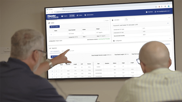
These equations are complex, so engineers today use calculation-based software or specialized spreadsheets to manage their tension calculations. Some companies use approximations in place of the complex formula. This comes from an era when this work was done by hand. Predicting cable tension allows for safer pulls that do not exceed the maximum tension of the cable. Good planning and predictive methodologies not only protect cable from excess tension, but they also increase worker safety and maximize the longevity of the cable through reduced tension and fewer splices or joints.
The Role of Polywater in Cable Friction and Tension Management
Cable friction measurement, pioneered by Polywater, supports accurate prediction of cable tension. Polywater has been measuring coefficient of friction (COF) and working with cable lubrication in the field for more than 50 years. Building on this knowledge has allowed a better understanding of the factors that influence tension to better plan for them. As the industry changes cable design and installation methods, test methods must reflect these changes. Long cable installations that are the hallmark of undergrounding were far less common when the Rifenberg equations were developed and when Polywater first started developing friction measurements. Today, Polywater is actively working with cable manufacturers and installers to adapt friction testing methods to more accurately reflect the realities encountered in the field.
| Learn More: Polywater Pull-Planner Cable Installation Planning Software |
Modern Cable Installation Techniques and Their Impact on Tension
Most cables are pulled into the duct using a winch. Typically, a pulling eye is attached to the cable end and its conductor. A swivel is inserted between the front end of the cable and the pulling rope to avoid torsional forces on the cable. Traditional installation methods and design have been augmented with newer techniques: long directionally drilled runs of conduit, cable pushing, and floating the cable in water-filled duct are three examples. These technologies impact the equations used to predict tension. There are cable tension and physics considerations for these types of design that differ from historical practices.
Tension Considerations for Long Curved Sections (Large Radius Bends)
 The Rifenburg bend equations assume that the cable is being “pulled” to the inside of the bend. When a cable is pulled into long lengths of curved ducts typical of HDD (Horizontal Directional Drilling) installations, the weight of the cable in the bend also increases. In this case, the gravitational force overcomes the vertical component of the pulling force. The cable no longer rides against the inside of the bend, rather it drops to the bottom of the conduit. The conventional equations no longer apply. The large radius bend acts much more like a sloped straight section of duct.
In the Polywater Pull-Planner, straight sections of the cable route are separated from the impending bends because the coefficient of friction acts as an add-on for straight sections but becomes a multiplier in the bends. The updated planning recommendation is to treat this section as a straight sloped section using a small horizontal bend to account for the slightly longer conduit length. In this case, the sidewall tension is minimal and can be neglected. Using this approach gives a better approximation of field realities and therefore of expected cable tension.
Long, curved sections require modified slope equations to better approximate the cable tension during installation.
| Related Content: Measuring Cable Pulling Friction with a Reel Test |
Cable Pushing: Tension and Buckling Risks
 Cable pushers were developed in the 1990s to achieve longer installation lengths. At higher transmission voltages, system reliability is critical. Reducing the number of joints is valuable. Furthermore, transmission cables typically have large diameter conductors and are stiffer by this design. The use of pushers can make sense for this type of installation and has continued to gain popularity as an installation method.
The standard cable tension equations still apply during cable pushing. In this case, the incoming tension used in the calculation is negative. The negative tension is carried through to each segment. In tests run by EPRI (Electric Power Research Institute), cables tested were not damaged by the pushing process. The main limitation of this installation method is cable buckling.
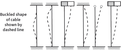
When cables experience excess pushing tension, they will bend or buckle within the conduit system. They will either create a wavy shape, spiral against the conduit wall, or crumple into a pile. In this case the pushing force is no longer transferred to the far end of the cable. Instead, the force further compresses the cable effectively creating a plug in the conduit. Cable pushing forces should not exceed the buckling force of the cable. Understanding the physics of cable buckling becomes critical to a successful installation.
Critical Buckling Force
Critical buckling force is based on Eulers formula and the cable’s modulus of elasticity. In other words, it is important to know the cable “stiffness” factor. Generally, this factor is influenced by the type of conductor metal, the stranding design, and cable size. There are predictive formulas based on both calculation and experimental design.
The key to effective cable pushing is to keep the force below the critical buckling force. Pushing force increases with higher friction between cable and conduit wall. The use of cable lubricants increases the effectiveness of cable pushing because they lower the likelihood of cable buckling.
When designing a route with cable pushing, the cable’s buckling force should be calculated.
Floating Cable in Water-Filled Duct: Buoyancy vs. Drag
 At times, either fresh water or salt (sea) water is added to the conduit to add buoyancy and effectively lower the weight of the cable. Lowering cable weight is a good way to lower pull tension because it reduces the normal force on the cable. It is important that the conduit system be properly sealed so that the water does not leak. It is also possible to fill just a portion of the conduit system to float the cable through the more difficult sections of the pull.
There is still a friction consideration during this type of installation. Cable lubricants can increase performance, as the cable still contacts the conduit surface. In planning this type of installation, there is water drag (frictional resistance) to consider. Another unknown is the force of water displacement. The effects of water drag and water displacement are complex to calculate. Often a conservative COF is used as a safety factor in these installations. Practical experience has shown this to be an effective style of installation especially for long, difficult cable pulls.
Pulling through water can lower cable weight through the buoyancy factor. Water drag and the force of displacement are negative factors that must be considered during tension planning for this type of installation.
| Related Content: Underground Cable-in-Duct Installation: 5 Trends to Consider |
Adapting Tension Models for Modern Installations
A good understanding of COF as well as the physics of the design are important aspects of planning cable installations. Recognizing that modern installation methods such as large radius bends, cable pushing, and water floating all present unique variables that need to be accounted for in tension calculations, Polywater continues to research ways to reduce friction in these areas and adapt that data into updates of the Pull-Planner software. In addition, users can measure and record the ending tension of in-field cable installations, input them into the Polywater Pull-Planner software, and back-calculate field COF. This can provide more practical tension data for future installations that utilize similar methods and materials. Back calculating COF can also be an efficient way to account for these variables without needing to calculate them individually, thus creating more accurate future cable tension calculations.
Selected Bibliography and Timeline
1943 Pulling Tension During Cable Installation in Ducts or Pipes, F. H. Buller
1953 Pipe-Line Design for Pipe-Type Feeders, R. C. Rifenburg Presented to the AIEE Insulated Conductor Committee
1983 EL-3333 Maximum Safe Pulling Lengths for Solid Dielectric Insulated Cables Published by EPRI
1984 Coefficient of Friction Measurement Between Cable and Conduit Surfaces Under Varying Normal Loads, G Weitz Polywater presentation to Transmission & Distribution Conference.
1991 A New Cable Pulling Friction Measurement Method and Results, J.M. Fee
1996 TR-106500 Cable Pushing and Calculation of Pulling Tensions for Distribution and Transmission Cables Published by EPRI
1999 A Study of Tension and Jamming When Puling Cable Around Bends, J.M. Fee
2001 CIGRE TB 194 Construction, Laying and Installation Techniques for Extruded and Self Contained Fluid Filled Cable SYstems
2022 CIGRE TB 889 Installation of Underground HV Cable Systems